WEE Technology Company Limited
We are WEE, We Enhance Efficiency
Manufacturer of Diode Rectifier, Bridge Rectifier, Transistor
How to test the bridge rectifier in a simple way?
Commonly used bridge rectifier detection methods
1, Static Test
(1)
Test the rectifier circuit to find the P and N terminals of the
internal DC power supply of the inverter, adjust the multimeter to
resistance X10, connect the red meter to P, and the black meter to R, S,
and T respectively. There should be approximately Resistance value of
tens of ohms, and basically balanced.
On the contrary, connect
the black meter rod to the P terminal, and the red meter rod to R, S,
and T in turn, with a resistance value close to infinity. Connect the
red meter stick to the N terminal and repeat the above steps, you should
get the same result.
If there are the following results, it can
be determined that the circuit has been abnormal, A. The resistance of
the three-phase imbalance, can indicate the rectifier bridge failure. B.
When the red meter rod is connected to the P terminal, the resistance
is infinite, and it can be concluded that the rectifier bridge is faulty
or the starting resistance is faulty.
(2) To test the inverter
circuit, connect the red meter rod to the P terminal, and the black
meter rod to U, V, W respectively. There should be a resistance value of
several tens of ohms, and the resistance value of each phase is
basically the same, and the reverse phase should be gigantic. Connect
the black meter rod to the N terminal and repeat the above steps to get
the same result, otherwise it can be determined that the inverter module
is faulty
2, Dynamic Test
After the static test result is normal, the dynamic test can be performed, that is, power on and test the machine.
The
following points must be paid attention to before and after power-on:
1. Before power-on, confirm whether the input voltage is wrong.
Connecting the 380V power supply to the 220V-class inverter will cause
explosions (fried capacitors, varistors, modules, etc.) . 2. Check
whether each broadcast port of the inverter is properly connected, and
whether the connection is loose. Abnormal connection may sometimes cause
the inverter to malfunction, and in severe cases, it may explode.
3. Check the fault display content after power-on, and preliminarily determine the fault and cause.
4.
If no fault is displayed, first check whether the parameters are
abnormal, and after resetting the parameters, start the inverter under
no-load (no motor connection), and test the U, V, and W three-phase
output voltage values.
If there is a lack of phase, three-phase
unbalance, etc., the module or drive board is faulty. 5. When the output
voltage is normal (no lack of phase, three-phase balance), load test.
When testing, it is best to test at full load.
WEET produce and
supply the most popular Flat and Square Bridge Rectifiers, contact us to
get more solutions of procurement, test, development.
50A 1000V: KBPC5010 BR5010 GBJ5010
35A 1000V: GBPC3510 BR3510
10A 1000V: GBU1010 GBJ1010
6A 1000V: GBU610 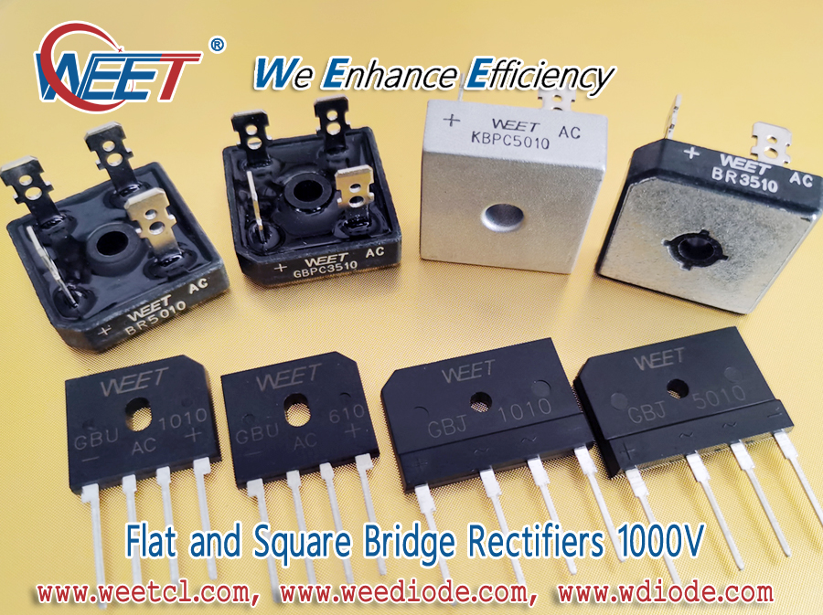 more product support: https://weetcl.com/Products/
Skype, Email: info@weediode.com
Written by WEE Technology Company Limited
WEET Flat and Square Bridge Rectifiers 6A 10A 35A 50A 1000V KBPC5010 BR5010 GBPC3510 BR3510 GBU1010
WEET Flat Bridge Rectifiers 1000V 6A 10A 50A GBJ1010 GBU1010 GBU610 GBJ5010 Single Phase Bridge
WEE Technology Company Limited
We are WEE, We Enhance Efficiency
Manufacturer of Diode Rectifier, Bridge Rectifier, Transistor
WEET Flat Bridge Rectifiers 1000V 6A 10A 50A GBJ1010 GBU1010 GBU610 GBJ5010 Single Phase Silicon Bridge
There are four types of bridge rectifier packages: square bridge, flat bridge, round bridge, and patch MINI bridge.
Square Bridge Rectifiers main packages: BR3, BR6, BR8, GBPC, KBPC, KBPC-W, GBPC-W, MT-35 (three-phase bridge).
Flat Bridge Rectifiers main packages: KBP, KBL, KBU, KBJ, GBU, GBJ, D3K.
Round Bridge Rectifiers main packages: WOB, WOM, RB-1.
SMD MINI Bridge Rectifiers main packages: BDS, MBS, MBF, ABS.
Connect
the positive poles of two diode rectifiers (set this junction point as
A) to form a series branch, and connect the negative poles of the other
two diode rectifiers (set this junction point as B) to form another
series branch, and then connect the above two branches in parallel (set
the two branches and the connection points are respectively C and D),
and the formed circuit is a square bridge rectifier. Also called a
single-phase bridge rectifier circuit. AC power is input from C and D
terminals, DC power Output from A (positive) and B (negative) terminals.
The
Bridge Rectifier is made up of four rectifier silicon chips for bridge
connection, and externally packaged with insulating plastic. The
high-power bridge rectifier is encapsulated by zinc metal shell outside
the insulating layer to enhance heat dissipation. There are many
varieties of bridge rectifiers: flat, round, square, bench-shaped
(in-line and patch), etc. The maximum rectified current ranges from 0.5A
to 100A, and the maximum reverse peak voltage ranges from 50V to 1600V.
The Bridge Rectifier is generally used in full-wave rectifier circuits, and it is divided into full bridge and half bridge.
The
half bridge is to seal the half of the two diode bridge rectifiers
together. Two half bridges can form a bridge rectifier circuit, and a
half bridge can also form a full wave rectifier circuit with a center
tap of a transformer. The full bridge is composed of 4 diode rectifiers
connected in the form of a bridge full-wave rectifier circuit and
packaged as a whole.
The forward current of the full bridge has
various specifications such as 0.5A, 1A, 1.5A, 2A, 2.5A, 3A, 5A, 10A,
20A, 35A, 50A, etc. The withstand voltage (the highest reverse voltage)
is 25V, 50V, 100V, 200V, 300V, 400V, 500V, 600V, 800V, 1000V and other
specifications.
1000V Single Phase Silicon Flat Bridge Rectifiers 6A GBU610, 10A GBJ1010 GBU1010, 50A GBJ5010 are used the most widely.
Consult us more information: https://weetcl.com/Single_Phase_Bridge_Rectifiers/ 
more product support: https://weetcl.com/Products/
Skype, Email: info@weediode.com
Written by WEE Technology Company Limited